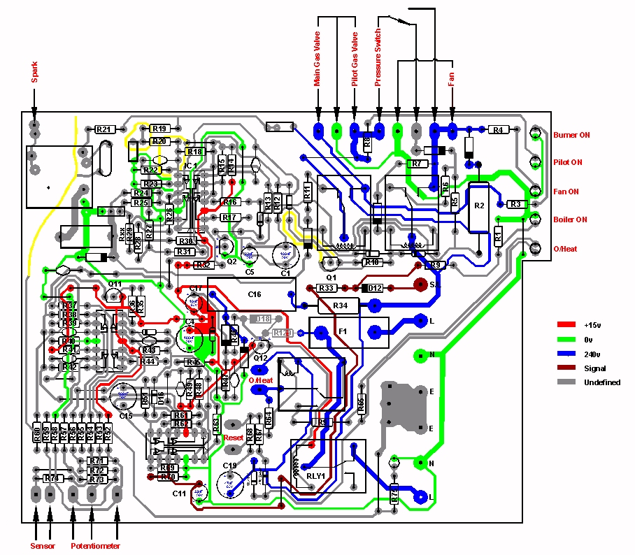
BaxiPCB Component Layout
BOILER PCB REPAIR PROJECT by Jon Edison
Just a few notes regarding my repair to a Baxi PCB.
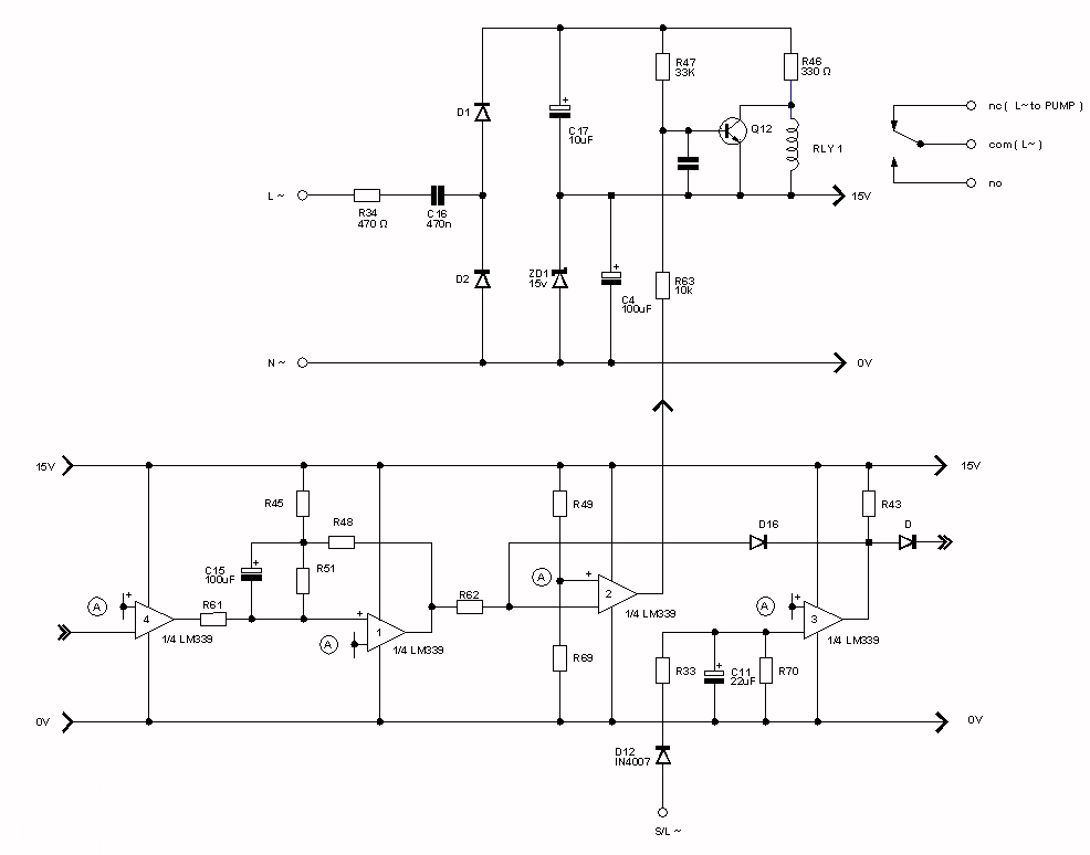
A common fault with the Baxi Central Heating Boiler is that a 'failure' on the pcb causes the Central Heating Pump to run continuously. I have three boards all with this same fault. I have said 'failure' in this way, as a check on all the associated components on the board appear to reveal no faults. I have traced the board out, and include the relevant circuit diagram here.
The circuit reveals that the Pump is driven from Relay 1. When the Boiler is running, this Relay is not powered, and the pump is fed from a pair of normally closed contacts. After the boiler shuts down, and approximately 5mins later, the relay is powered up, the contacts open and the pump stops.
This operation is achieved via transistor Q12. When the Boiler is being called for heat, this transistor is ON, which pulls the voltage on R46 down, and prevents RLY1 from operating. The Pump is now ON fed from the pair of normally closed contacts. When the Boiler is turned OFF, there is a 5min delay before the transistor base is pulled low via an output on a LM339 Quad Comparitor. This turns the transistor OFF, energising the Relay, and consequently turns the Pump OFF.
My checks suggest that the transistor powers off as described above, but the Relay fails to pull in.
This relay has a 24v coil, the specification can be found here. Using a test circuit, the minimum voltage to switch the relay was found to be 15.7v. This is lower than the minimum spec suggested on the data sheet of 16.8v ( 70% of 24v ) . So the relay is well within specification. The only conclusion therefore is that there is less than 15 or so volts available.
Why this occours is not clear. My suspicion is that the relay operation has always been marginal, and a general deterioration in some of the associated componets eventually leads to a drop in the supply voltage, and subsequently the relay fails to operate. The test circuit mentioned above also suggests that the voltage was never too high either. The current through R46 when the transistor Q12 is ON, using the theorectical minimum voltage of 16.8v as the supply, gives 51mA ( I = V/R). This is very high, and is well above the resistors power limit of 0.6W ( P = I x I x R). So the circuit probably never operated with the voltage this high in the first place. Thus my comment that the circuit was marginal from the start.
The power supply to the relay and other electronics, is obtained via R34 and C16. These drop the 240v mains voltage to around 30v or so, which is then fed to a pair of Diodes D1, D2. These act as a simple halfwave rectifier. One half feeding the Relay, and the other half limited by the 15v Zener, feeding the electronics. Again, all the components in this chain check out OK, but once mains is applied, I suspect the dynamics of one or more components must change.
Jon Edison
July 2011
Update Dec 2011
Capacitor C16 has now been replaced and the Relay is now functioning again!
The relay pulled in after a delay of approx 5mins
Capacitor obtained from Rapid Electronics part number ref 10-2685 ( or 10-2782 )
Update Nov/Dec 2012
Capacitor C16 part number changed.
Rapid Electronics ref is now 10-2782 only.
RS Components part number is 148-424. Thanks to Gary for the information.
CPC ( Farnell ) part number is CA07098 . Thanks to Steve for the update
BaxiPCB Component Layout
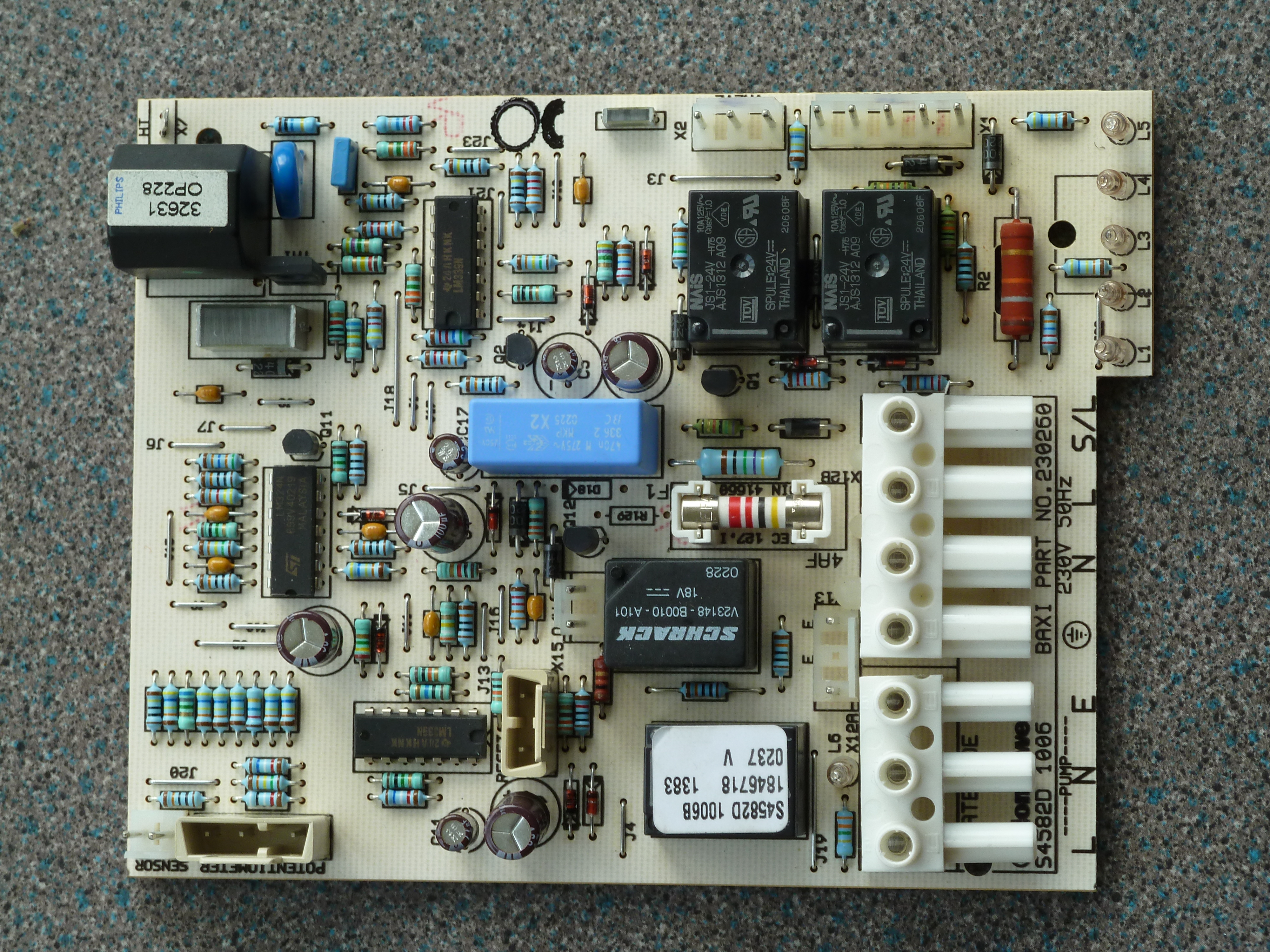
Baxi PCB