
F3F TIMER PROJECT by Jon Edison
Updated Dec 2016
MK III Bluetooth Interface
<Back
Investigations into a Bluetooth Interface proved to be straight forward and relatively easy to construct using ready made modules. The Software for the Android was developed and a Bluetooth Interface was added in Dec 2016.
Bluetooth Interface
The Android Race software now supports Bluetooth for the communications with the Timer. An additional carrier board with a HC-05 Bluetooth Module is required. This board and module simply replaces the IOIO board previously used and plugs into the same pcb connector. ( The Author can provide pre-programmed modules and carrier board if required ). If you prefer to source you own, full construction details are given below.
Bluetooth modules of the type HC-05 are readily available, and come packaged ready to go. Some programming may be required to the Baud rate if you are using this module with our earlier Timer software, but this is easily achieved using an Arduino UNO described below. The bluetooth modules come with instructions, but there is slight differences between them, so make sure you follow the instructions that come with your module when programming.
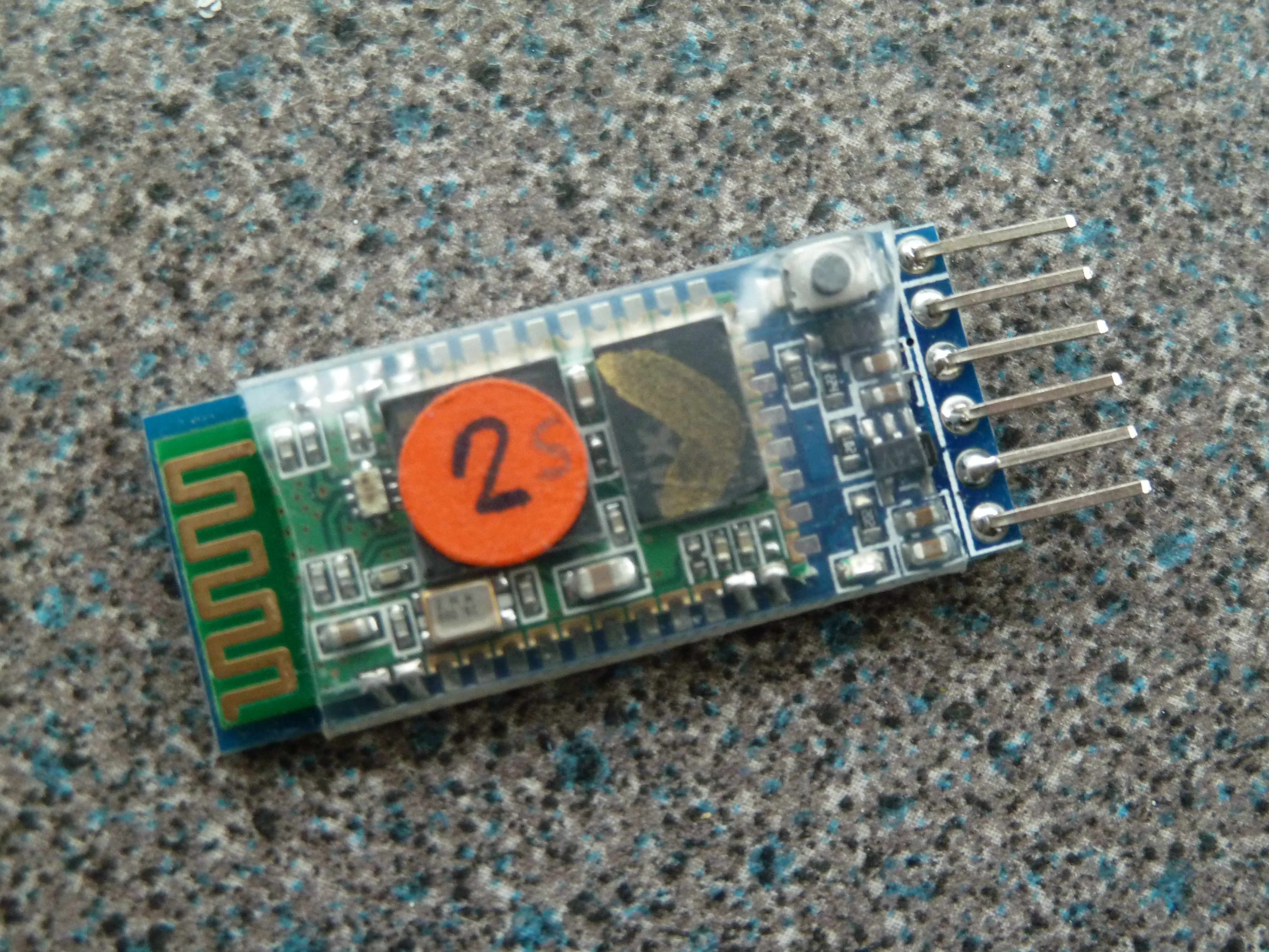
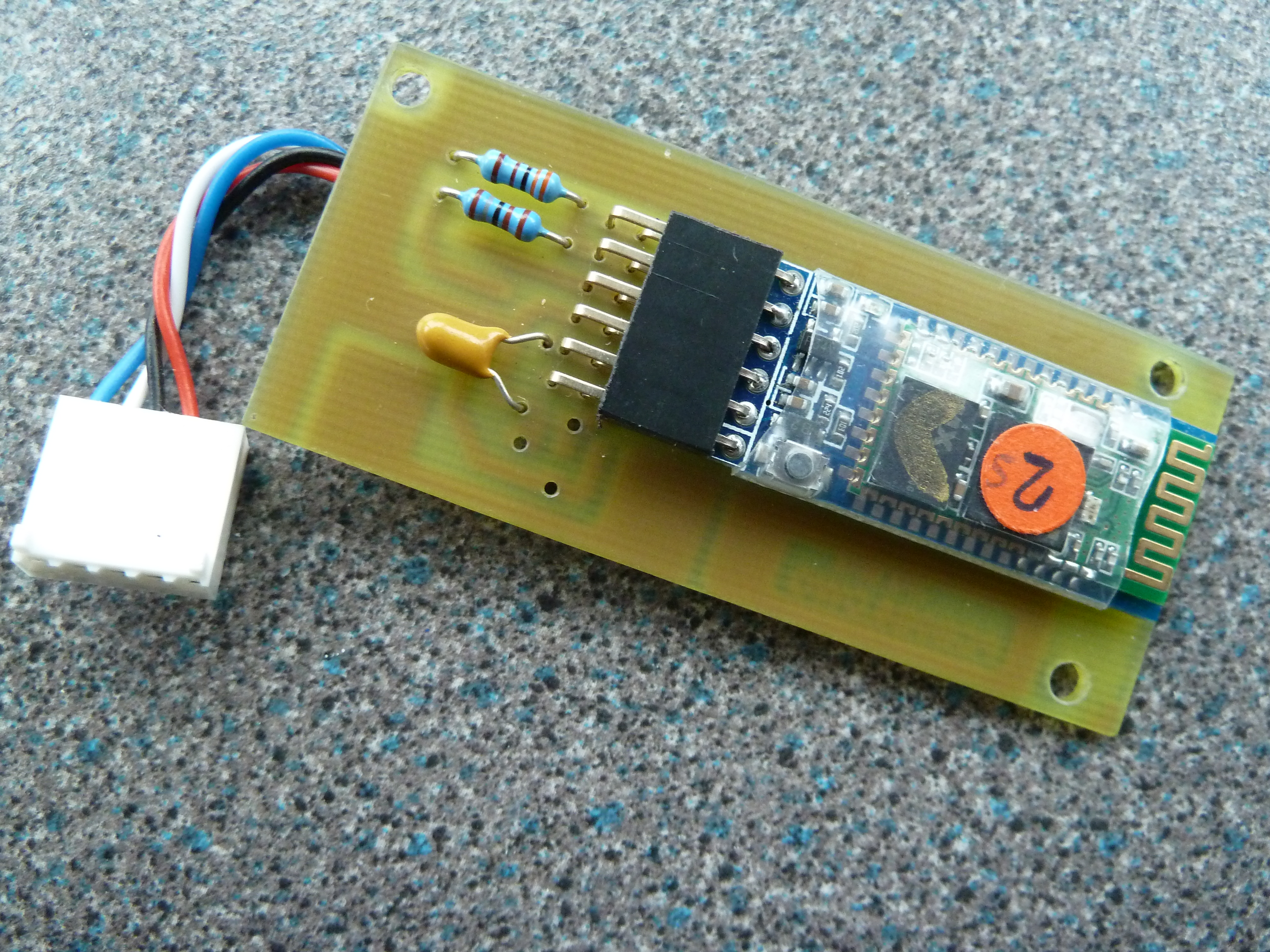
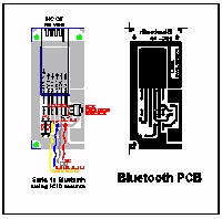
Here the HC-05 has been mounted on a carrier board for final connection to the Timer. The carrier provides voltage and signal conditioning for the Bluetooth module. The PCB layout for the carrier board is shown full size from the component side. Produce the PCB using a photo etch process, and drill all holes 0.8mm. NB the 5v regulator is a SMD device and is soldered to the copper side of the board. All other components are through hole mounted. Connect the cables and 5pin molex plug, and mount the board using the IOIO mounts on the main PCB.
The latest Timer firmware as of December 2016 ( v5.8 and above ) will communicate with the Bluetooth modules at their default baud rate of 9600, and therefore they will work without modification.
These modules can be used with the earlier firmware, but they will need to be re-programmed. This requires either a serial port, a serial to USB adaptor, or an Arduino UNO. The following method uses the Arduino approach, but the principal is similar which ever serial device you choose. Click here for details
Connecting the Bluetooth Module to the Android
Once the Bluetooth Modules has been attached to the Timer PCB, it is necessary to 'pair' the Android and Timer. Switch-on both the Timer and Android, and go to the Bluetooth settings in your Android.
Switch on Bluetooth and look for nearby devices.
'F3FTimer' should be found. [ Default name will be different ] .
If a password is required, enter '1234'.
The Timer and Android should now pair.(the LED on the module will double flash)
Return to 'Race Manager'.
From the drop down menu ( top right of the Screen -3 vertical dots ),
Select 'settings', Select 'input source',
Select 'Bluetooth - HC-05' [ Baud rate setting not important ]
The Timer and Android should now communicate via Bluetooth. [ The Red Dot on the screen just below the Menu vertical dots will turn Green to indicate a working connection].
The Timer is now ready to race!
The IOIO board used previously, provided via the USB port enough current to maintain the Android throughout the day. Unfortunately the Bluetooth Interface doesn't provide any charging current, so three alternatives methods of charging are shown below :-
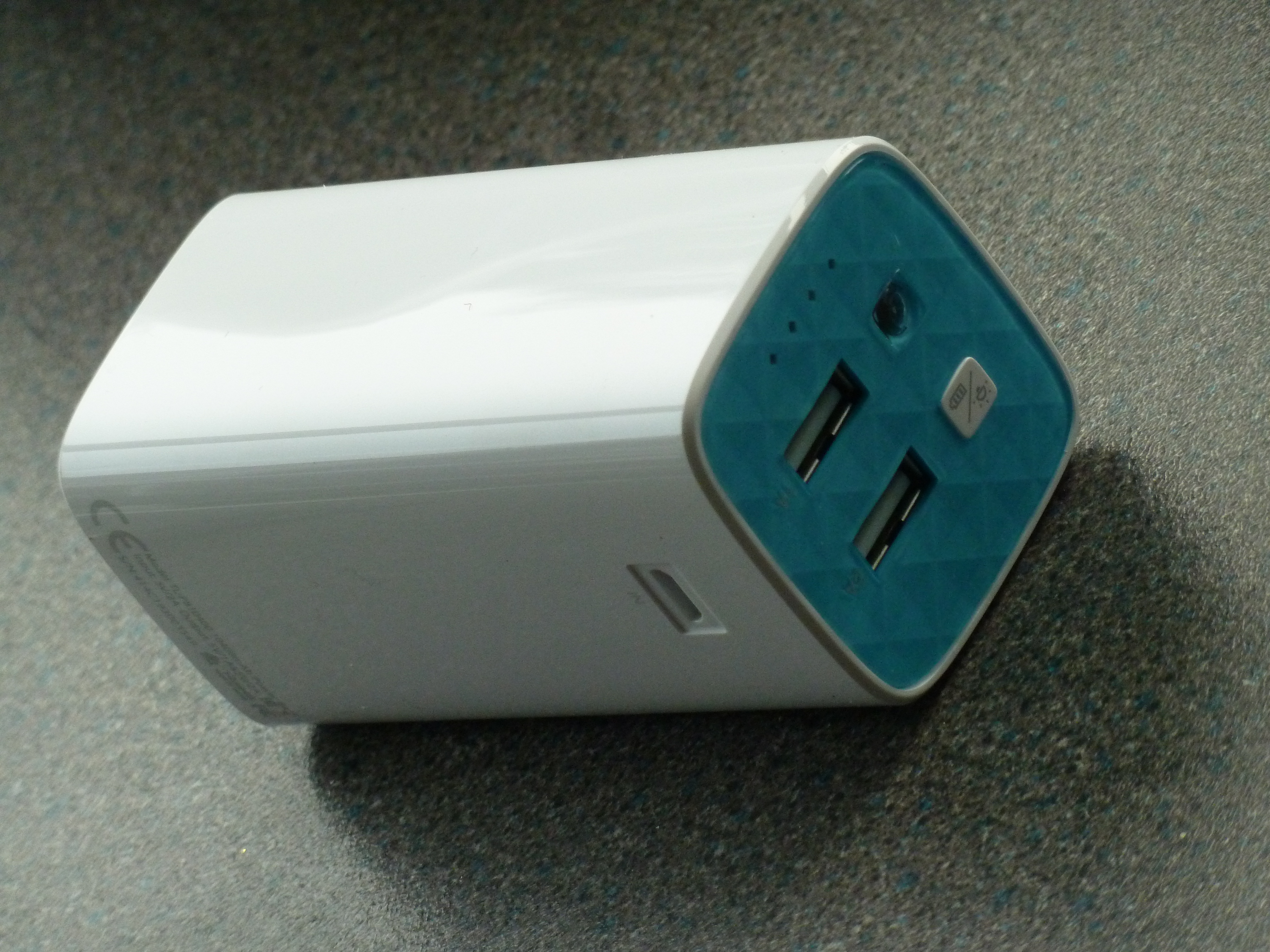
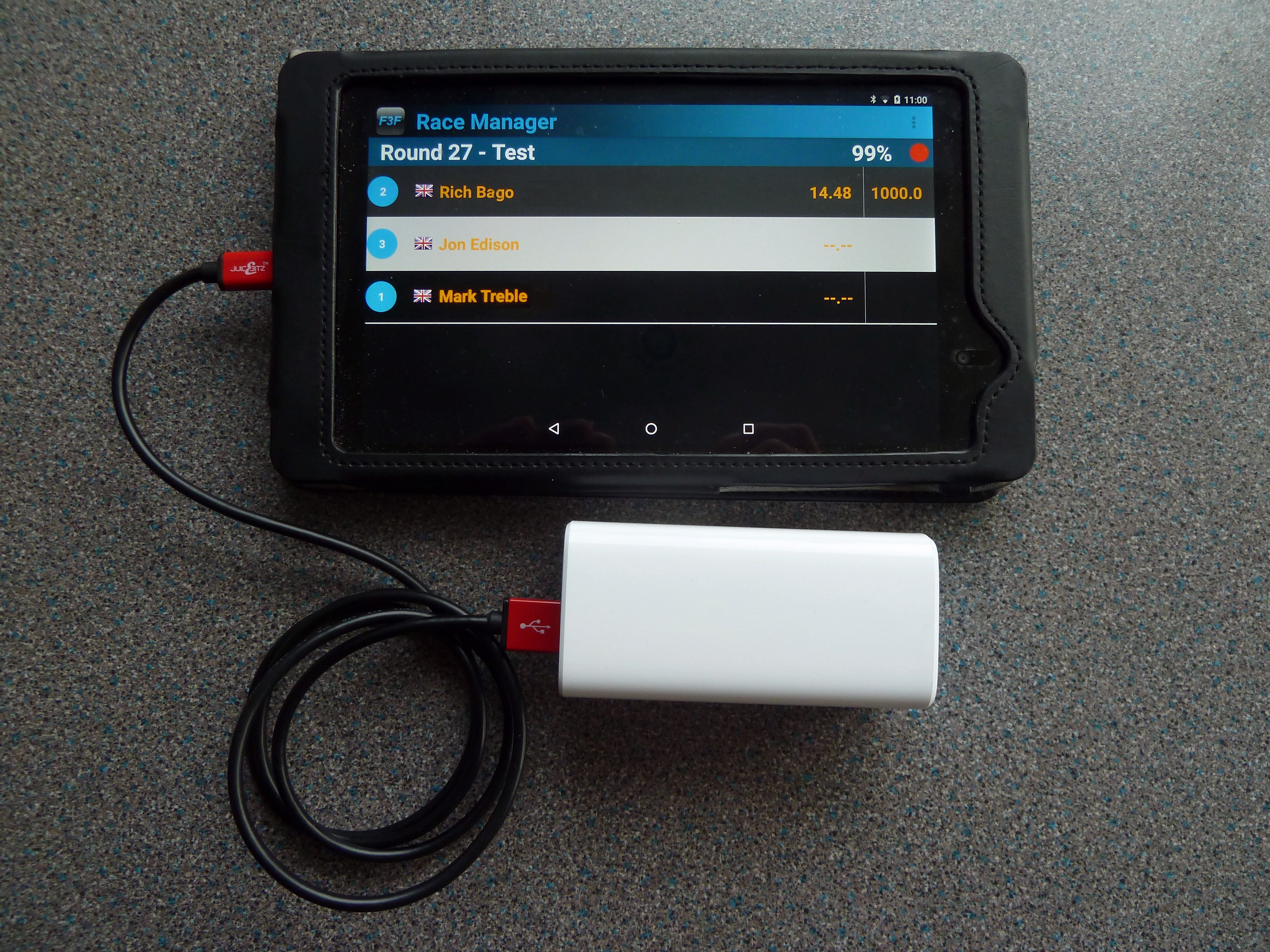
1) Power Pack. This is a battery pack with a built in USB port. Simply connect the Andriod to the Power Pack with a regular USB cable and adequate charging is achieved for the day. There are numerous sizes of power packs available. This picture shows a TP-Link 10400 power pack, connected directly to the Android. The TP-Link unit has also been used for powering the Bluetooth Speaker system. This is the simplest of all the charging methods.
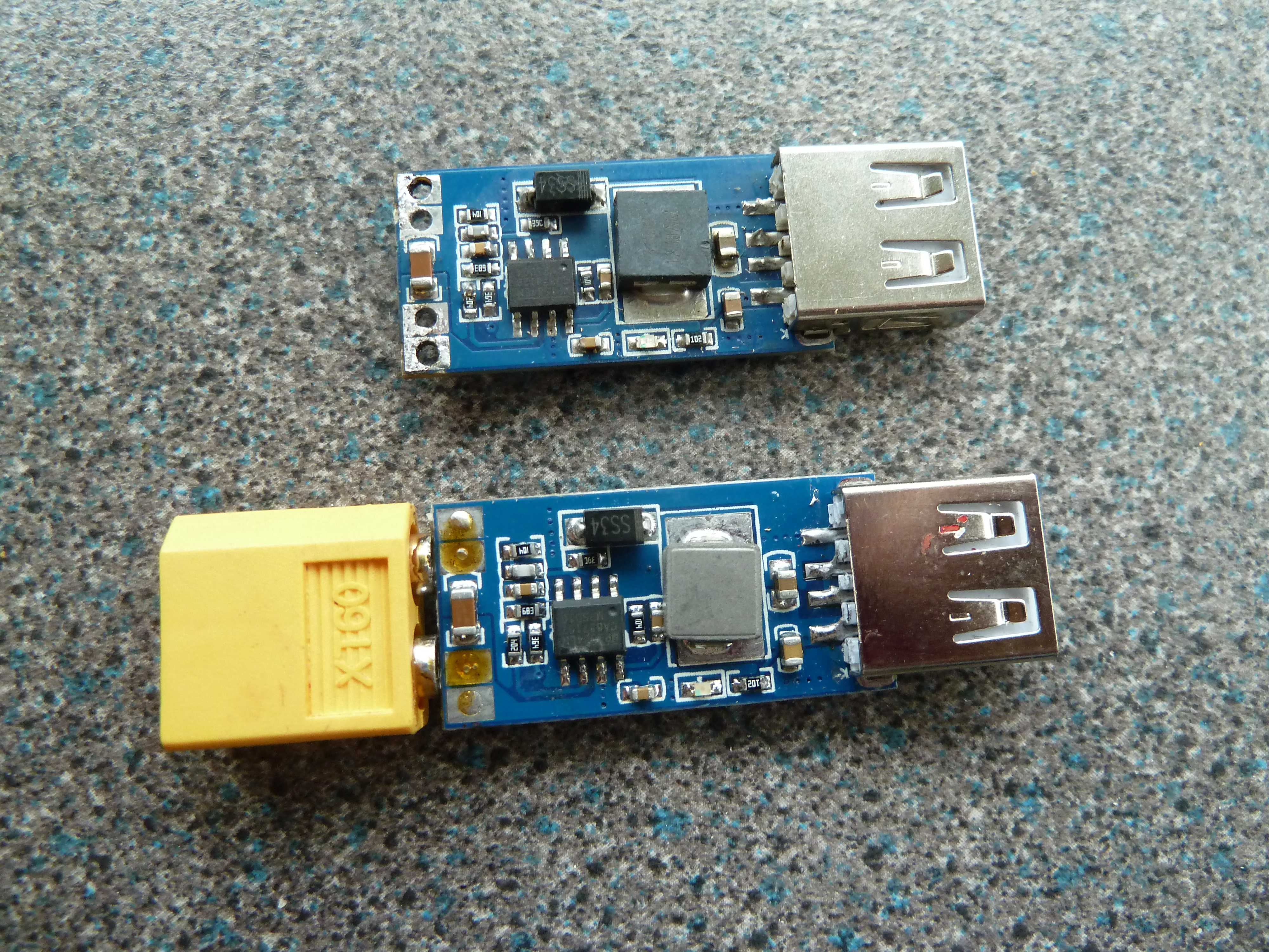
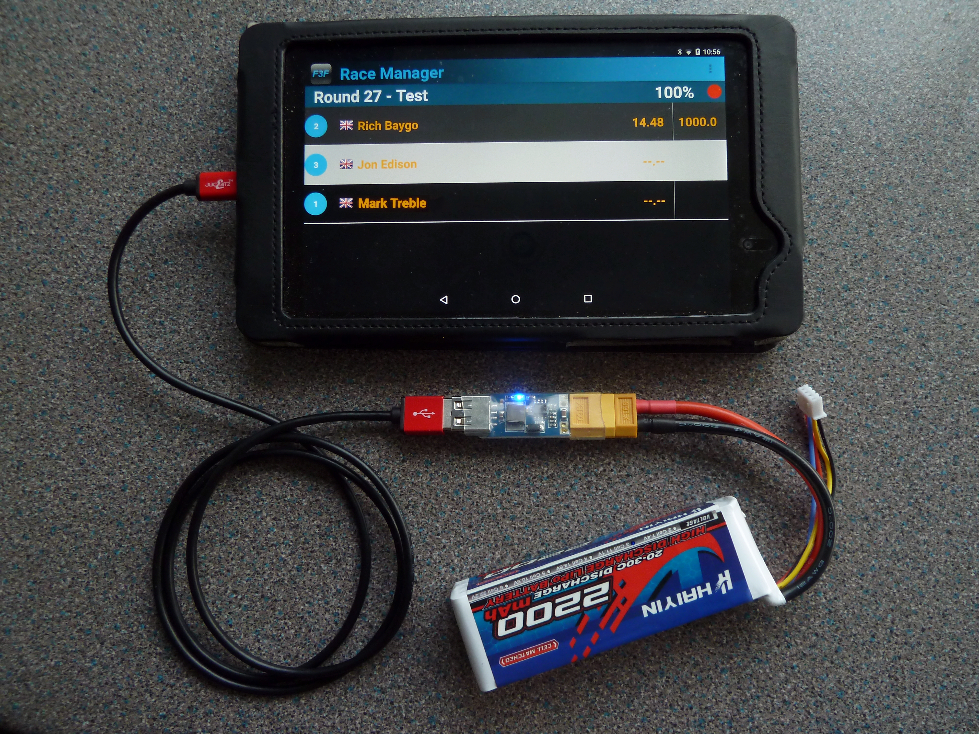
2) USB Charger. These are small devices which can be connected to any battery with a voltage in the range of 9-24v. They provide up to 2A charging via a USB port, and can be found on eBay for a few pounds each. Here an XT60 connector has been added to one of these devices and then connected to a spare 3s Lipo battery pack. A cheap solution as it can be used with one of the spare Timer battery packs described on a previous page.
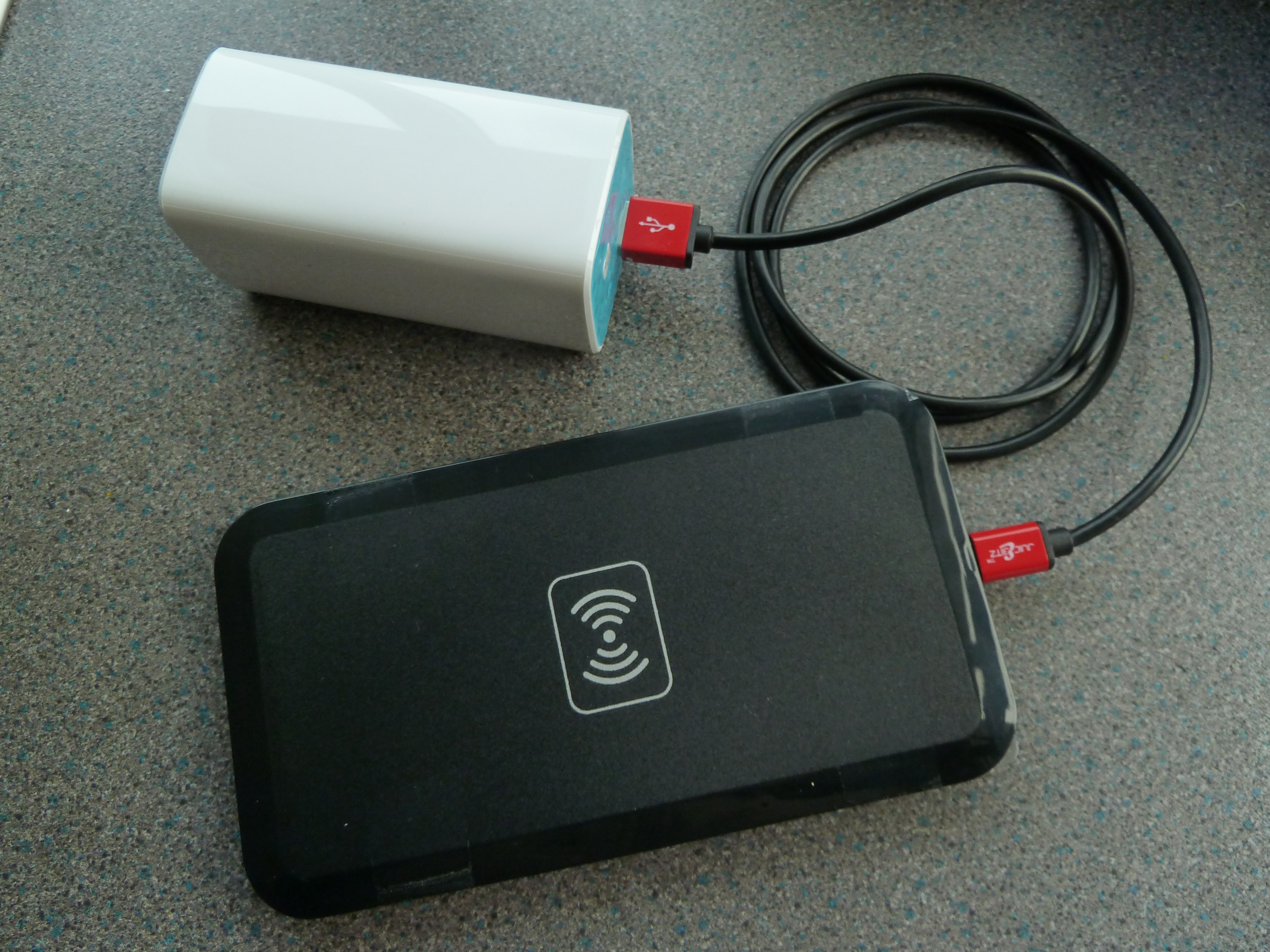
3) QI wireless charging pad. The Android must have facilities for QI charging. These provide contactless charging but still require the use a power source, here shown with the TP-Link Power Pack as described above. Positioning of the QI pad against the Android is critical for maximum charge rate, and fixing the pad to the Android via sticky tape is the best way to achieve this. This gives adequate charging but the convenience of contactless charging is lost due to the need to fix the charger in position.
Return to Top
Return to Previous Page
Programming the Bluetooth Module
Details for programming the 6 pin modules only is given. The 4 pin HC-06 variety require a slightly different approach, and the AT commands have a different syntax.
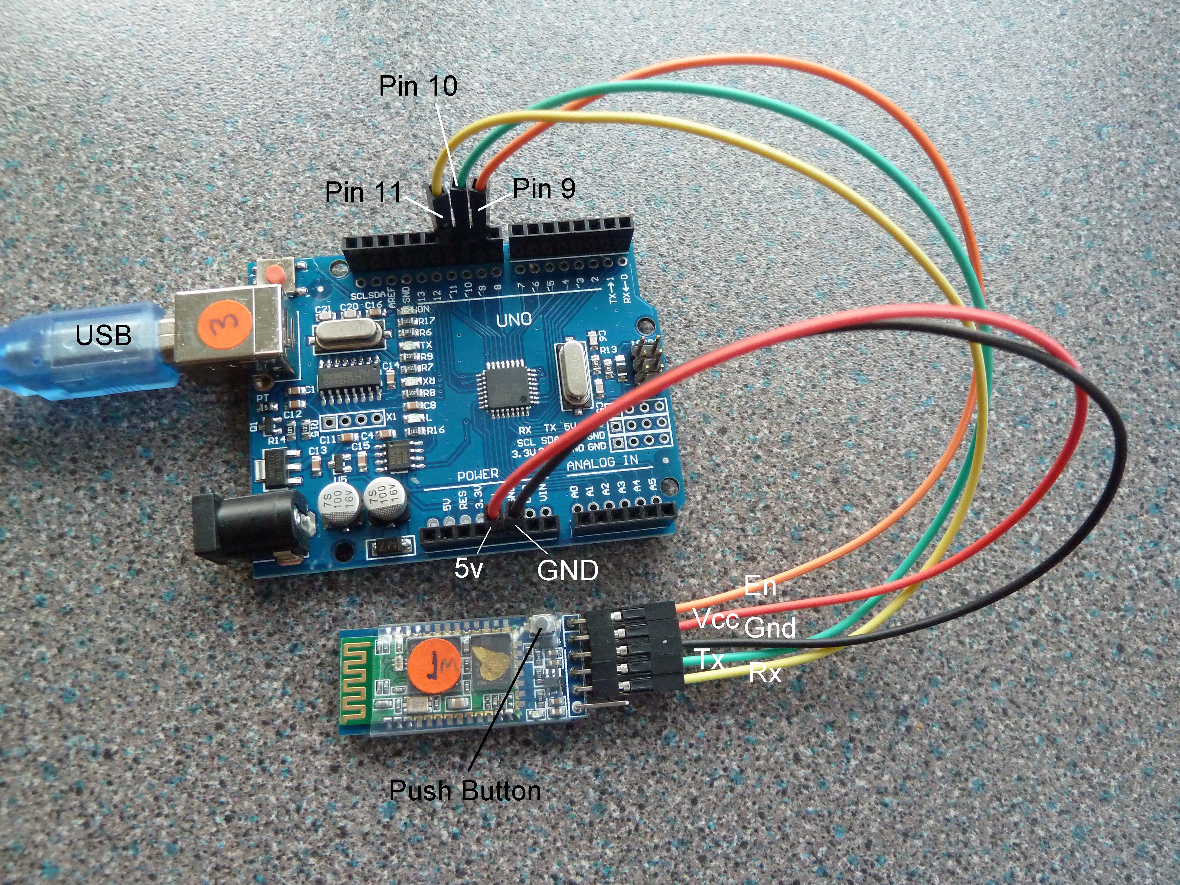
Above picture shows the Bluetooth module connected to the Arduino UNO board using breadboard connections wires, these being the most convenient and straight forward way to connect. The process for programming is as follows :-
Run the Arduino IDE program and upload the Arduino Sketch listed below
Disconnect the USB cable and connect the Bluetooth Modules as shown
Disconnect the 5V RED wire from the UNO before reconnecting the USB cable
Press and hold the PUSH BUTTON on the Bluetooth module, reconnect the 5v RED wire
Release the Push Button
The LED on the Bluetooth module should now be flashing slowly, showing that it is now in Programming Mode.Using the Arduino IDE program, open the Serial Monitor.
Set baud rate to 9600 and set the option for line endings to 'Both NL and CR'
The Arduino will respond with 'Enter AT Commands'
Now send the module the command 'AT'
Response should be 'OK'.If not, recheck connections and make sure the baud rate and line endings are correct
If all is well, ie 'OK' response from the 'AT' command is received , proceed as follows :-
Send the command 'AT+UART=2400,0,0' [ sets baud rate for earlier F3F timer comm's ]
Send the command 'AT+NAME=F3Ftimer'[ sets name of module, makes pairing more obvious]
Send the command 'AT+CMODE=0' [ sets communication mode ]
Send the command 'AT+ROLE=0' [ sets module as SLAVE, Default setting but just in case ]
Send the command 'AT+RESET' [ exits programming mode ]
All commands give the response 'OK'
Components required :-
Bluetooth Module HC-05 - Ebay
Arduino UNO - Ebay
Arduino Sketch ( Software available here )
Breadboard Connectors - Ebay
Disclaimer
I have no connection with any of the companies listed above, but give any links for information only, and for use at your own risk. All information is given in good faith and without liability.
Jon Edison
Dec 2016