
F3F TIMER PROJECT by Jon Edison
Created August 2022
MK III Design and Construction of USB Boards
<Back
1) IOIO Board v2
The IOIO board was a cleverly designed and constructed interface for many electronic projects where connection to, and control by, an Android Phone or Tablet via a USB port was required. Uniquely the IOIO board could be fitted with a Bluetooth Dongle and convert to Bluetooth seamlessly.
The F3F Timer was one of those such projects. Apart from providing a USB Charging Port, the IOIO board provides a USB to Serial ( RS232 ) conversion and a digital input for the push button 'Start' Function required by the Timer.
As an open source project, the IOIO board's design and Software is readily available to anyone wishing to construct a board for themselves. This page describes one such approach.
As only a limited number of connections are required to the IOIO board to control the Timer , the revised PCB was designed and constructed to have only these connections or ports.
These are :-
USB Type A Port
Pin 3 - Serial Port Rx
Pin 4 - Serial Port Tx
Pin 46 - Digital Input
In Addition, in order to Programme and Power up the board, the following connections are also required
MCLR - Programming Input
Pin 37 - Programming Input
Pin 38 - Programming Input
Vin - 8 to 15v Input
Gnd - Ground
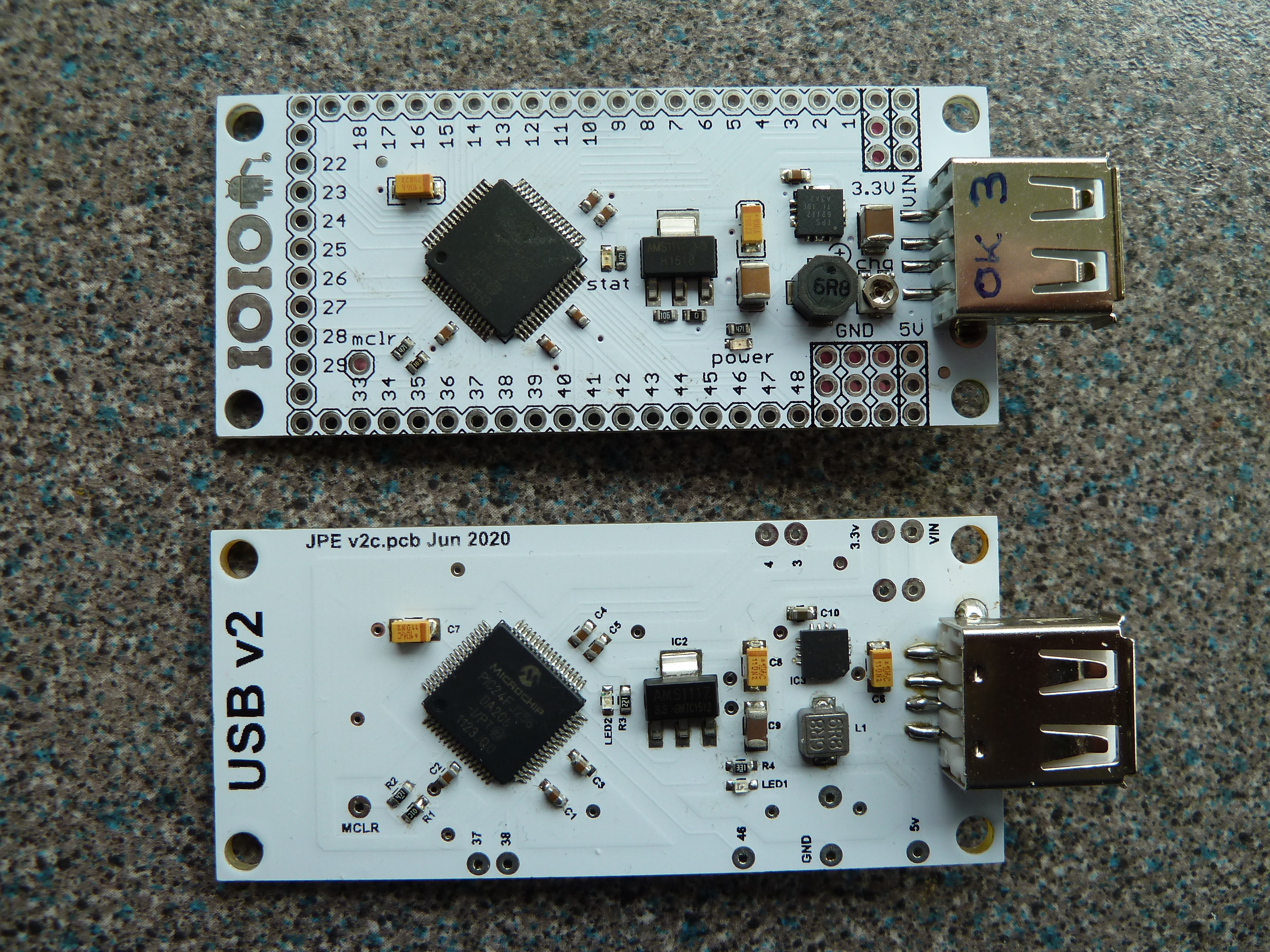
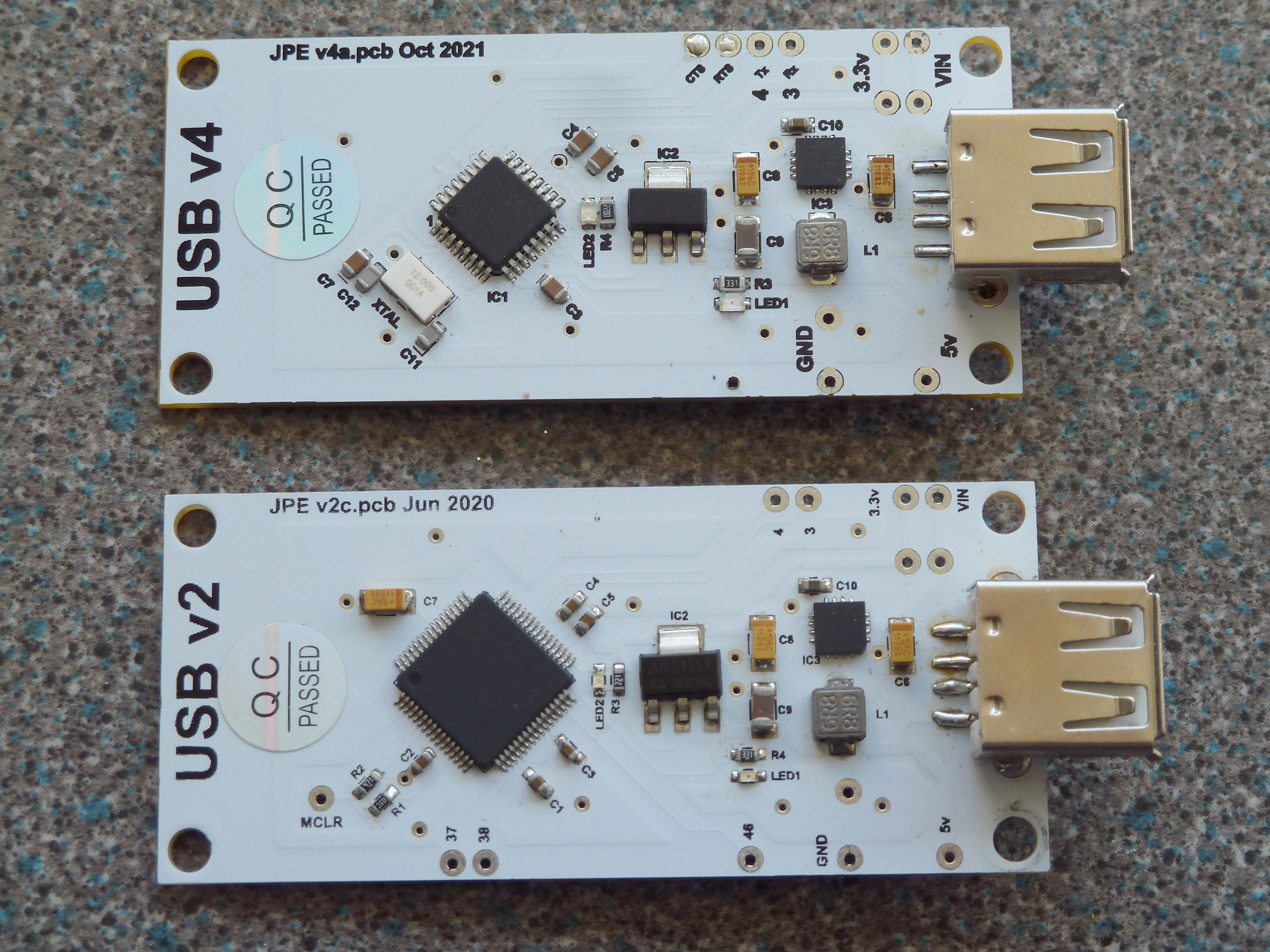
The resulting Board shown below, now named USB v2, with a 'standard' IOIO for comparison
The Printed Circuit Board itself is not designed for home construction and must be manufactured by a professional PCB Manufacturer. In order to do that, a series of drawings are required to facilitate manufacture.These drawings are available here for your use.
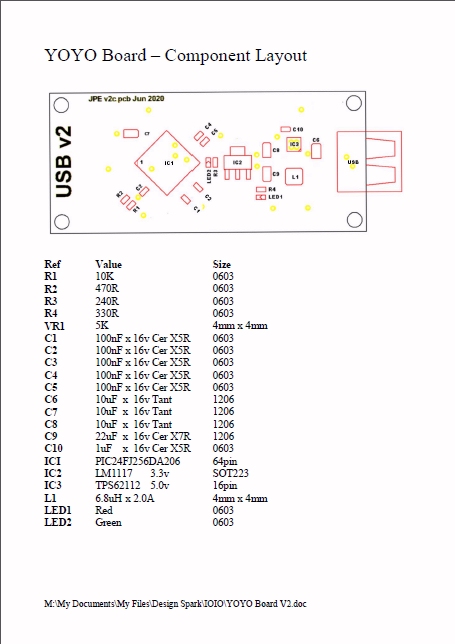
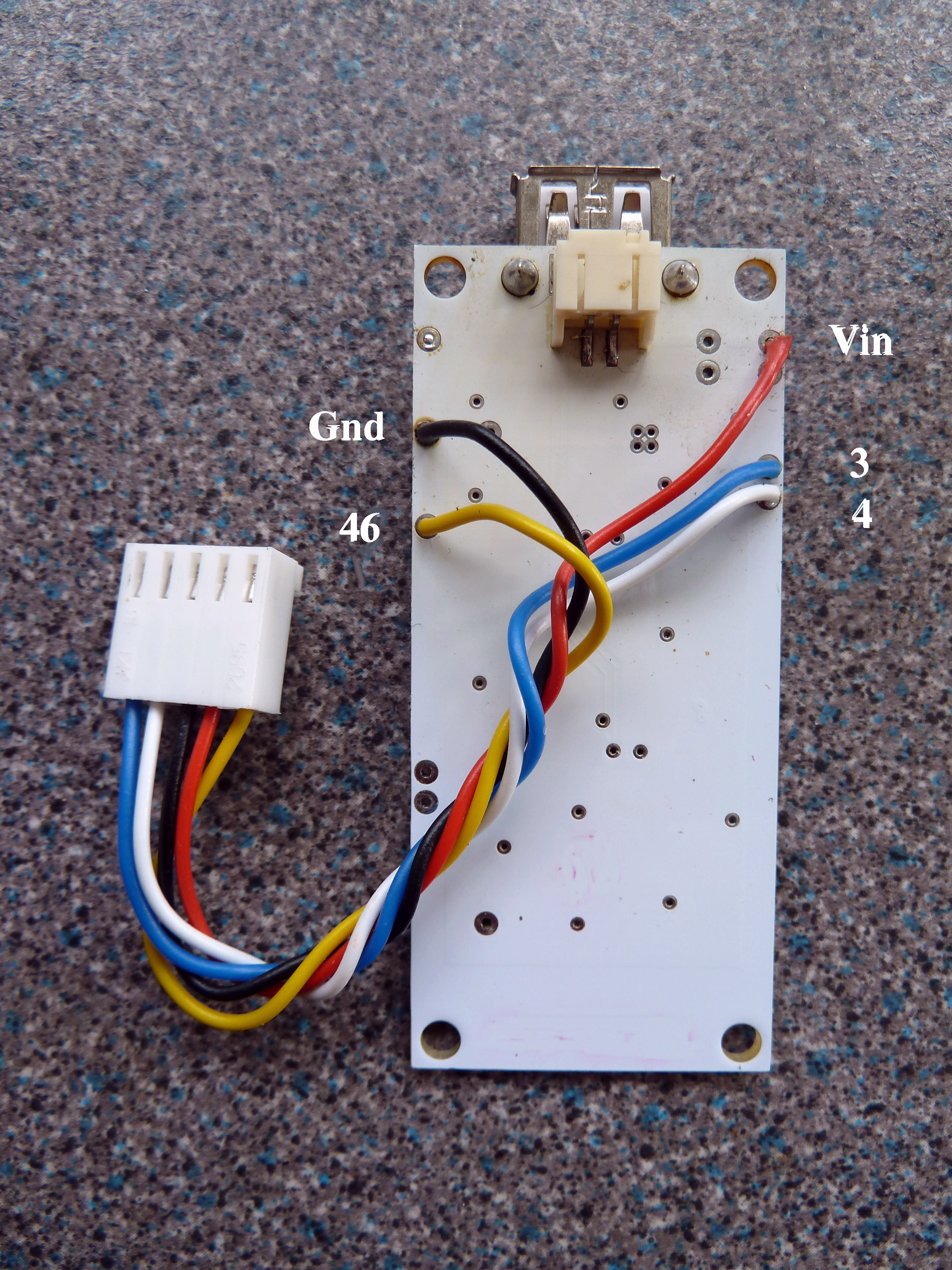
v2 Board Layout v2 Board Connections
Once constructed, check the following voltages are present.
5v indicated by the RED LED1 . If not re-check / re-solder IC3 connections
3.3v on Tab of IC2. NB Needs 5v supply to be present, If not , re-check IC2 connections
1.8v on positive end of C7 ( Pin 56 of IC1 ). If not then IC1 is probably not working, usually caused by poor solder joint to one or more pins, very carefully re-check / re-solder
If all is well, the board will need to be programmed, Details Here
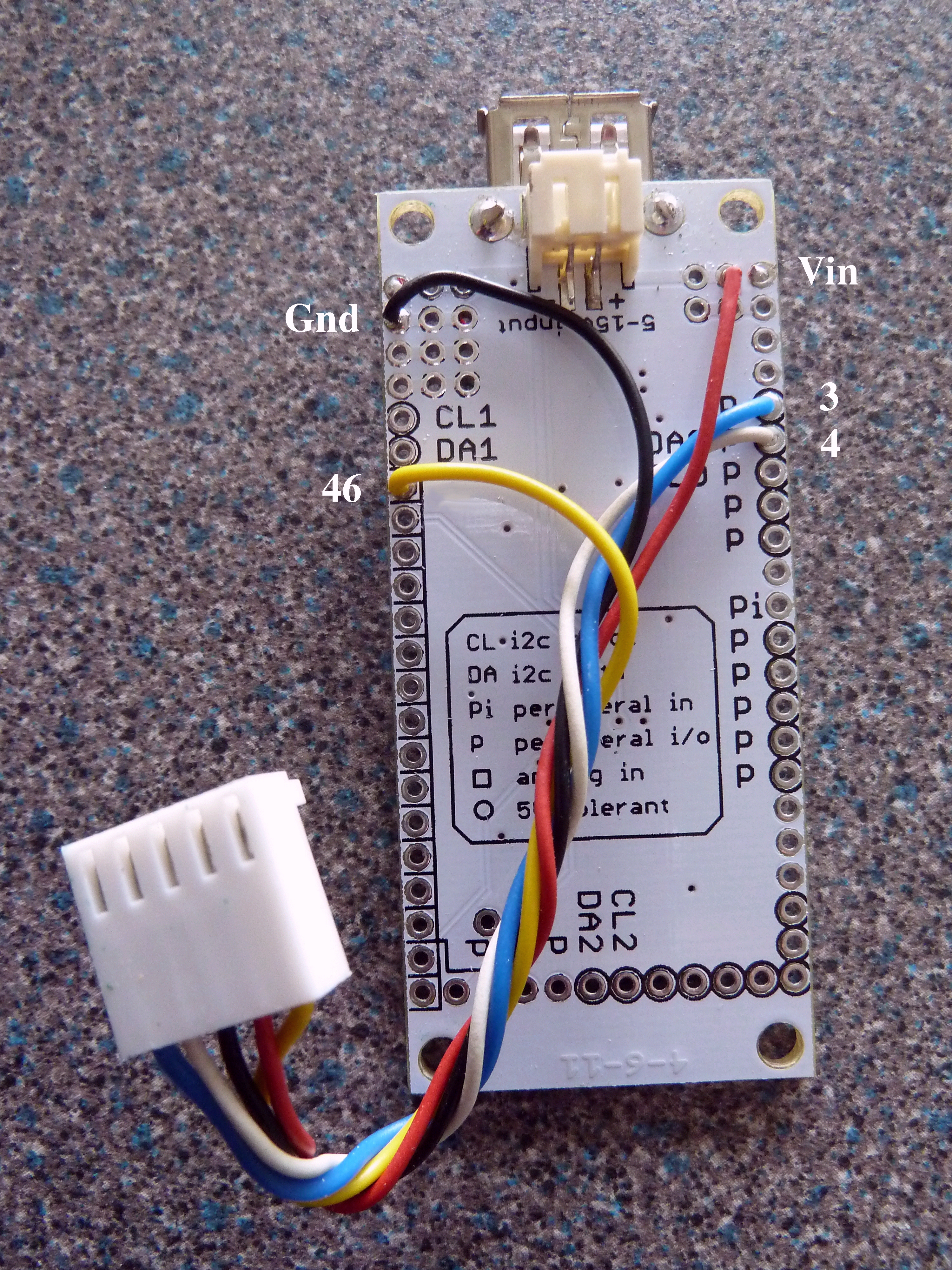
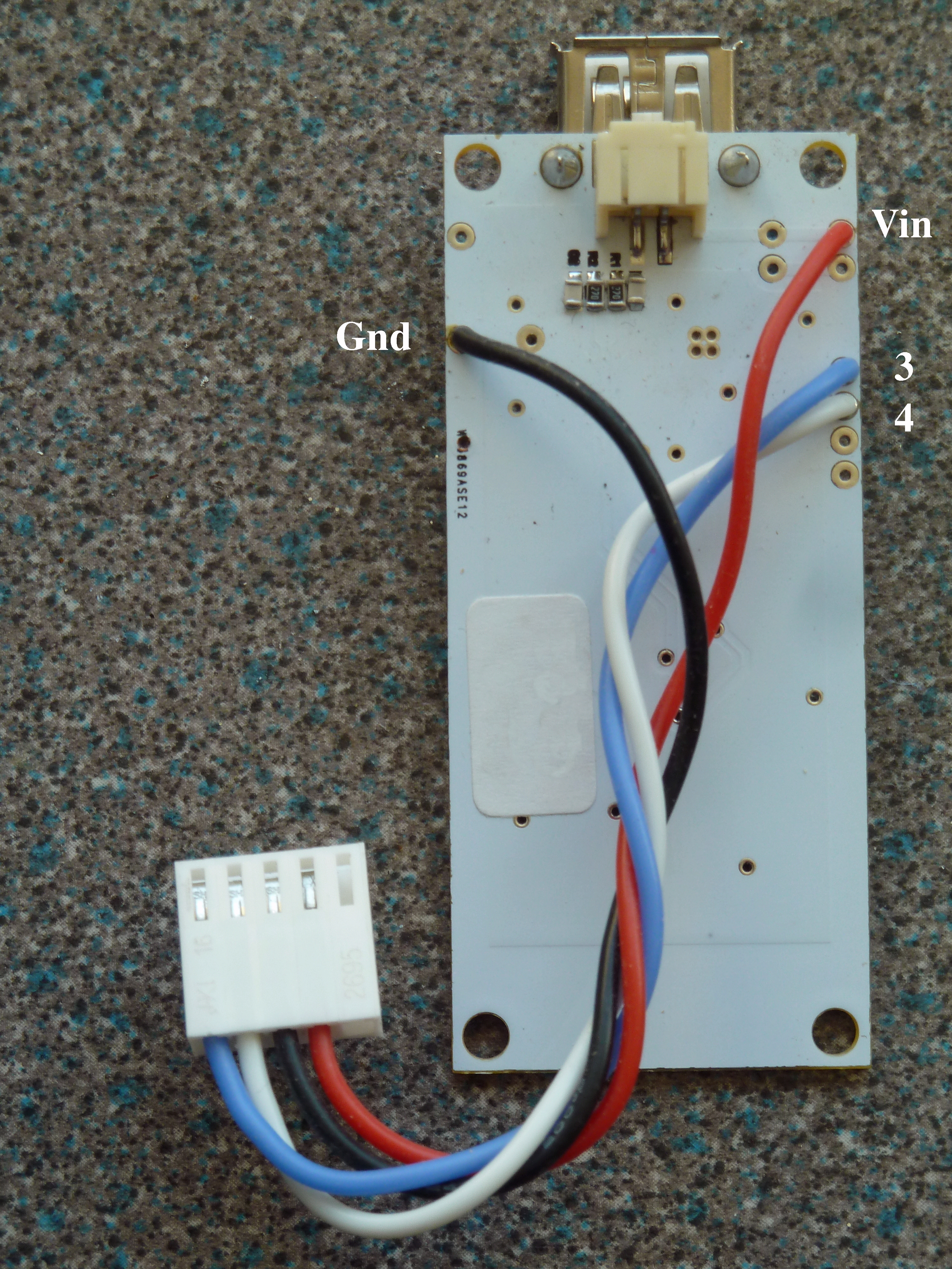
Board Connections
2) New Android Accessory Board with FTDI chip
This Board is a complete replacement for the IOIO that we have used in the past. It is based on the FTDI FT312D chip which was designed specifically for communicating with the Android OS
The F3F Timer requires a USB port for all the comms between it and the Android Tablet. This board provides that function, and as such requires only a limited number of connections.
These are :-
USB Type A Port
Pin 3 - Serial Port Rx
Pin 4 - Serial Port Tx
Vin - 8 to 15v Input
Gnd
- Ground
Also provided are CTS and RTS connections.
making the board useful for other projects, where these are required, but are not needed for this Timer,
The resulting Board is shown below, named USB v4, with the alternative USB v2 for comparison
The Printed Circuit Board itself is not designed for home construction and must be manufactured by a professional PCB Manufacturer. In order to do that, a series of drawings are required to facilitate manufacture. These drawings are available here for your use.
v4 Board Layout v4 Board Connections
The soldering of SMD ( surface mount devices ) onto a PCB is covered in detail on the Internet, but a brief overview is presented here.
There are a number of ways to solder SMD parts onto a PCB. The one chosen by the Author is to use a Reflow Hotplate. This is where all the components are assembled together on the PCB which is then placed on the Reflow Hotplate. The Temperature of the hotplate is increased in stages, following what is known as a 'reflow profile'. The solder paste that was applied at the assembly stage finally melts, soldering all the components to the board.
Construction of a Reflow Hotplate can be found here
Once constructed, the board will need to be programmed, Details Here
Disclaimer
I have no connection with any of the companies listed above, any links given for information only, and for use at your own risk. All information is provided in good faith and without liability.
Return to Top
Return to Previous Page
Jon Edison
Aug 2022